
Engineering Portfolio
A showcase of my projects and skills
I recently graduated from Montana State University with a BS in mechanical engineering and a minor in mechatronics. I'm passionate about robotics and automation, and enjoy working at the intersection of mechanical, electrical and software engineering.
Tension Testing Fixture
A project I worked on during an internship at Glowforge.
What
- Fixture to test the fatigue and instantaneous load failure criteria for an rtv silicone adhesive joint between two dissimilar plastic parts.
How
- A prototype for the fixture was designed in Solidworks based on the geometry of the parts that would be tested and the available equipment
- The prototype was designed to be 3D printed and fit into an Imada tension tester that was available, which already included a load sensor and linear motion stage
- The first prototype was 3d printed on a Stratasys printer. Performance of the prototype was assessed, and adjustments were made for a second prototype, which was then printed
Result
- The fixture was able to securely hold the parts during tension testing of the adhesive joint
- The fixture was handed off to the engineering team
Ideal Linear Rail Alignment Fixture
Another project I worked on during my internship at the company Glowforge.
What
- Test fixture allowing adjustment in 4 axes of linear rail alignment to simulate the impact of manufacturing tolerances on the performance of a linear motion system
How
- Mounts were designed to attach the existing linear rails to a precision breadboard plate with threaded holes
- The mounts allowed for minor adjustments of one of the rails in 4 axes using shims, and kept the other rail fixed in place
- Mounts were 3d printed for design verification, with the option to later machine them out of aluminum if greater precision is required
- Alignment measurements could be taken with an available Faro arm CMM
Result
- The mounts were able to securely hold the rails to the breadboard, and allowed for the desired range of motion
- The internship ended before any measurements could be performed with the Faro arm, and the fixture was handed off to the engineering team
UV LED Controller
This UV LED Controller was a component of my senior design project for my engineering degree. The overall project was a group project with three other students, but the UV LED controller portion shown below was done by me.
What
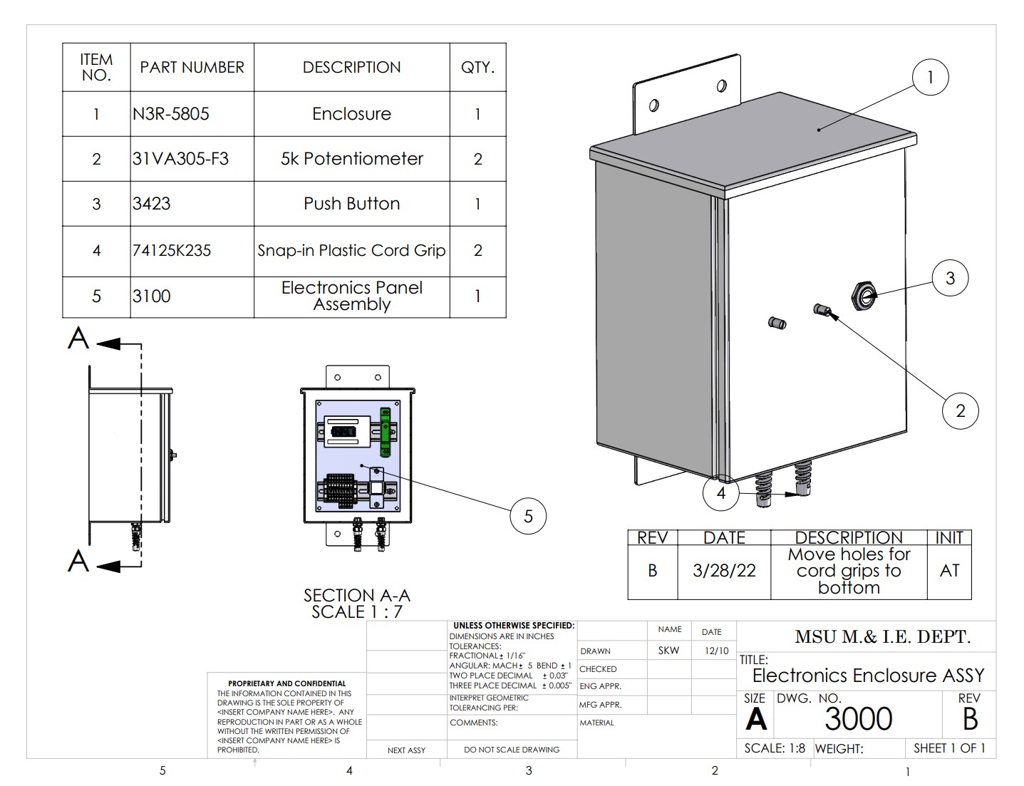
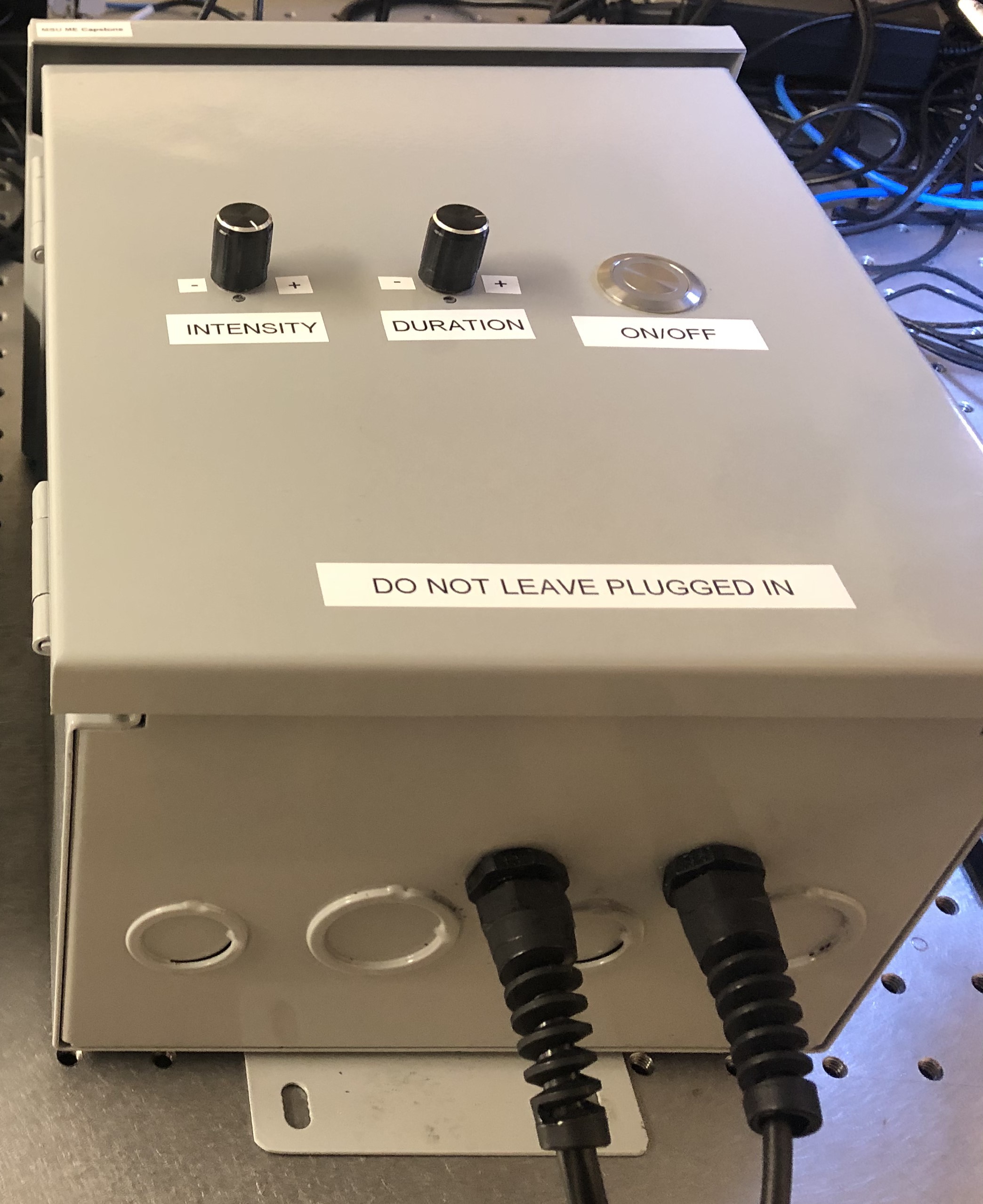
- Controller box for an ultraviolet LED light used to cure epoxy
- User had to be able to turn the light on and off, and have the light turn off automatically after a set amount of time
- Both the intensity of the light and the time duration had to be adjustable by the user
How
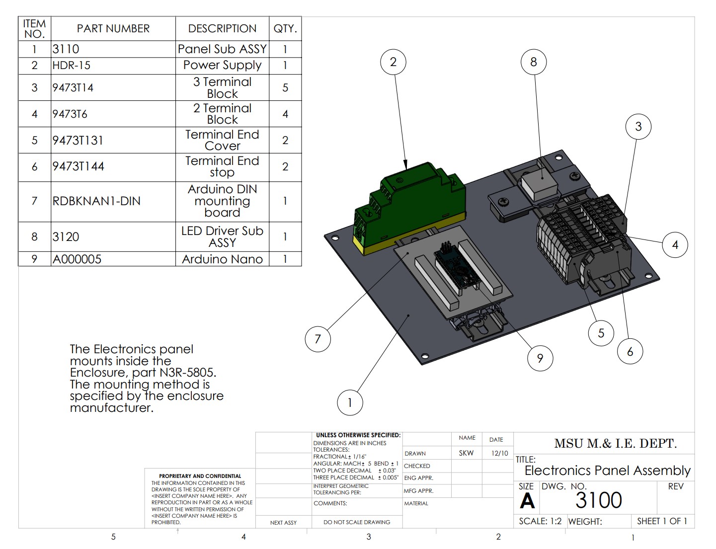
- LED driver specified based on the LED voltage and current requirements
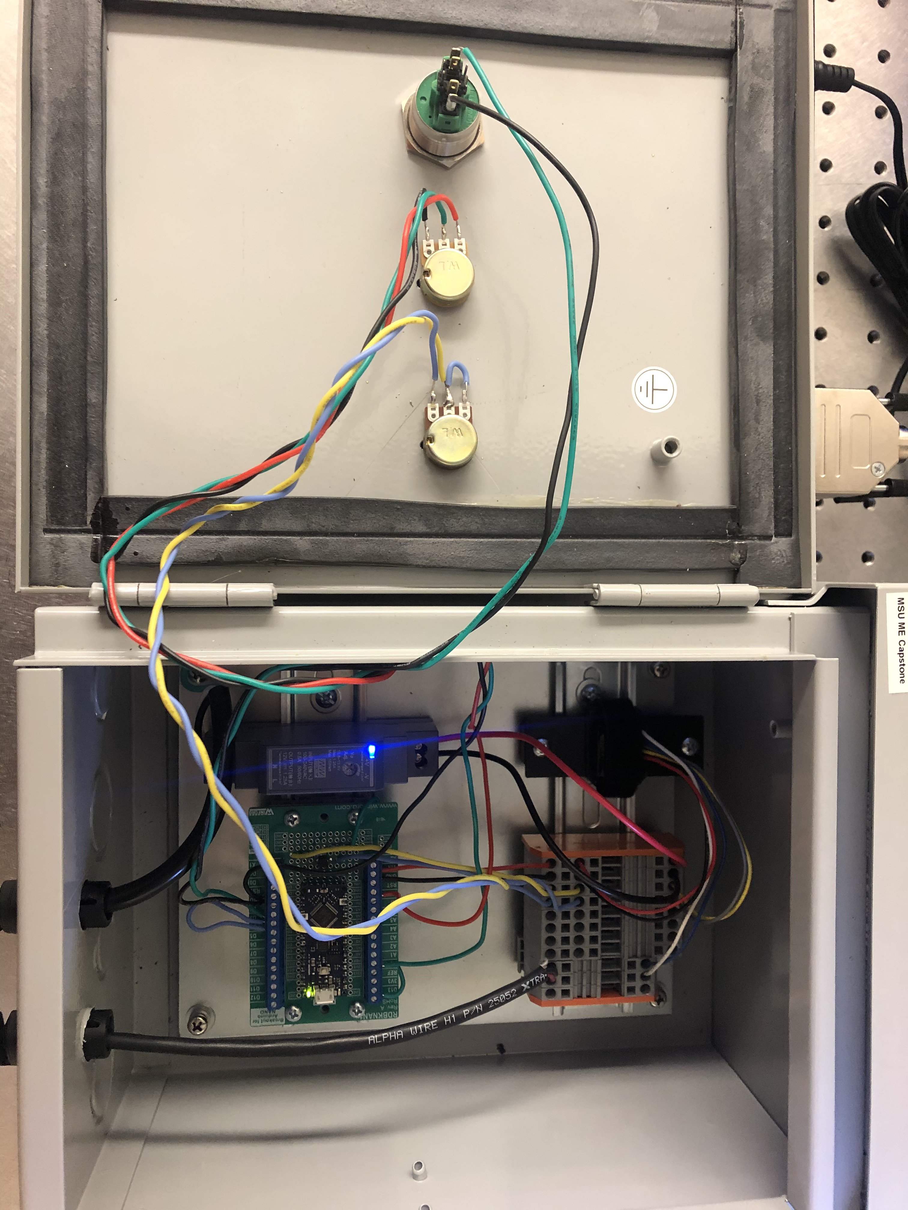
- 2 potentiometers were used for user input of intensity and duration, and a push button was used to turn the light on and off
- An Arduino was used to read the duration potentiometer and turn the LED off after the set time length
Result
- The driver functioned as intended, allowing for adjustment of both intensity and duration of the UV light, and turning on and off when the button was pushed, allowing for consistent curing of the epoxy
High Precision Actuator Selection
This was also a component of my senior design project, and this part was a collaborative effort, with all four team members contributing input into the decisions made.
What
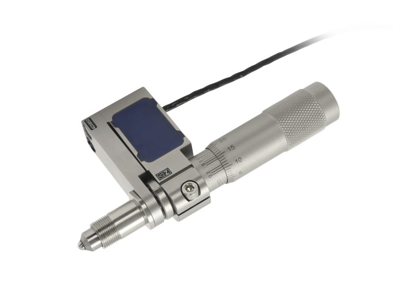
- Specify a linear actuator and controller to replace the discontinued actuator and controller in a high precision fiber optic alignment device
- The motor had to have a resolution of 100 nm, supply 50 N of force and have a linear travel of at least 12.5 mm
How
- We researched many different actuators and added them to a spreadsheet to directly compare
- We then created a decision matrix based on a set of parameters agreed upon by the group and based on the requirements given by the project sponsor
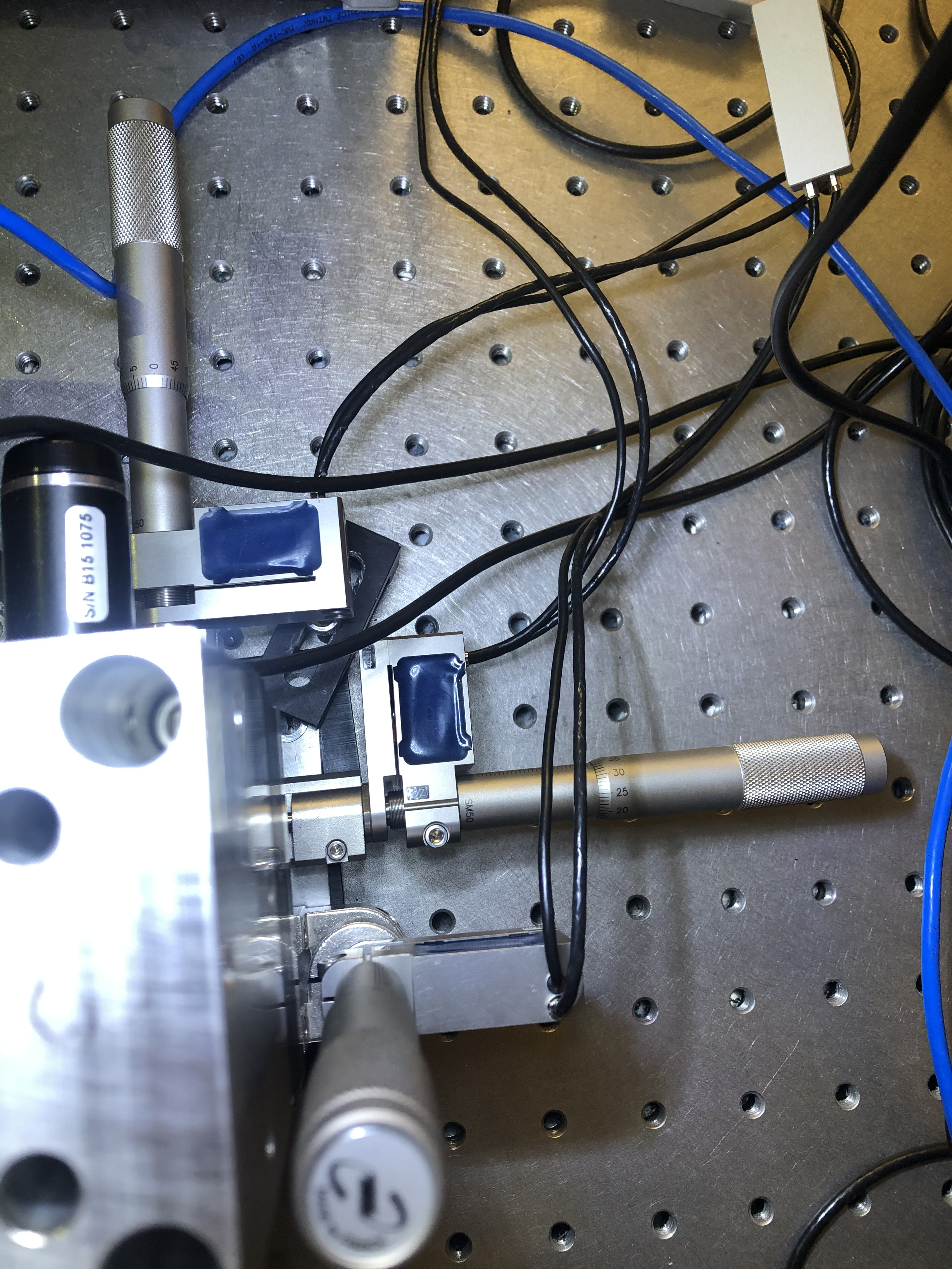
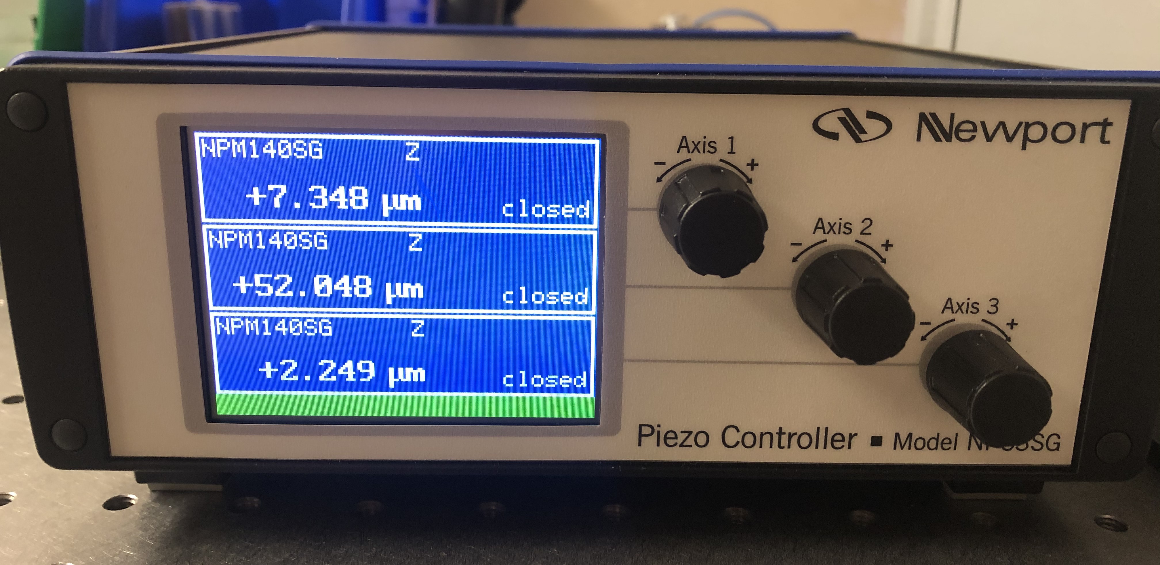
- Using the decision matrix, we selected a combination of a piezo-stack actuator with a manual micrometer. The piezo-stack provided very high resolution motion over a short distance, and the manual micrometer allowed for less precise motion over longer distances
Result
- The piezo-stack actuators were easily able to meet the 100 nm required resolution, and the manual micrometers had more range than the required 12.5 mm of motion
- There was some concern that the act of manually turning the micrometer might contribute too much disturbance to the system, but if this becomes an issue in the future, the micrometers can easily be replaced with high travel, low resolution actuators albeit at additional cost
Robot Drive Base
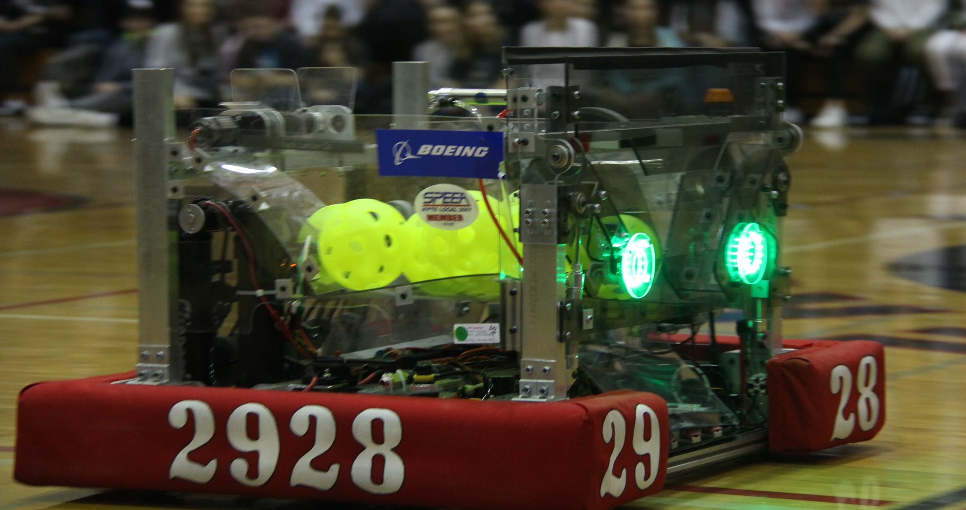
A project I worked on during my senior year of high school for my school's FRC robotics team, "Viking Robotics", FRC team 2928. I did the mechanical design and CAD for this project.
What
- Drive base for a roughly 150lb robot that allowed the robot to move around a field during competitions
- Had to allow for turning and precise control of the robot's position to achieve the competition objectives
- Had to be manufacturable given the tools and materials available to the team
How
- A six-wheel design with a 1/8 inch dropped center wheel was chosen to minimize resistance due to friction while turning
- Components were designed using Autodesk Inventor
- Smaller components were machined on CNC Mills, while larger plate components were cut on a waterjet
- Off the shelf motors and gearboxes were used to power the drivetrain, with belts connecting the wheels on each side to each other, so that all wheels were driven
Result
- The drivetrain sustained multiple collisions with other robots and field elements without failing
- Maintenance (e.g. changing wheel tread, replacing belts) was fast and simple
- The team was on the winning alliance for the FRC world championship in Houston, TX, as well as a district level event, thanks in part to the speed and reliability of the robot's drivetrain
RC Car
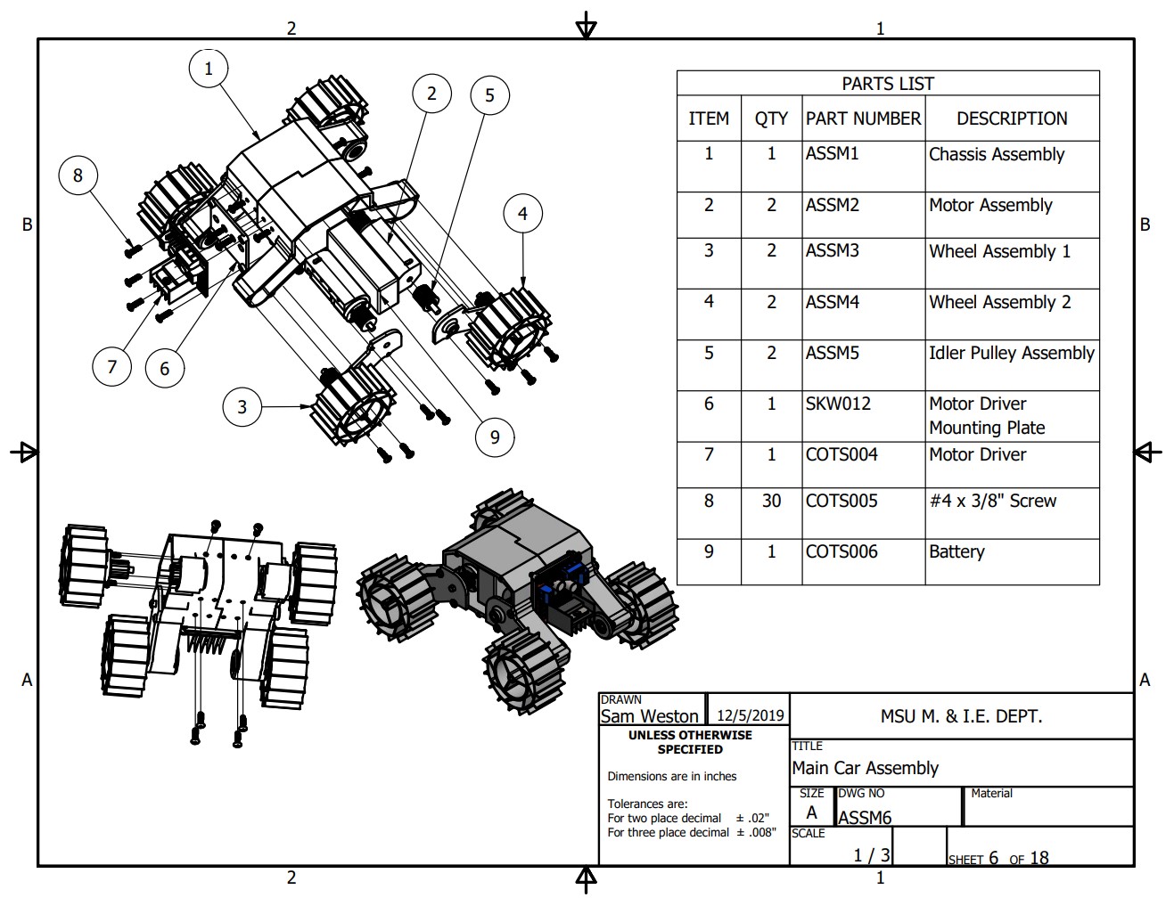
This was a semester long project for a multidisciplinary design class. All parts of the car were done by me.
What
- Design and build a small RC Car to drive through an obstacle course
- Had to fit within specified dimensions and weight
- Had to be able to climb a steep incline and maneuver over different types of rough terrain made from carboard and wood
How
- The car was designed in Autodesk Inventor
- The car chassis was 3d printed in PETG plastic and the wheels were 3d printed in compliant TPU
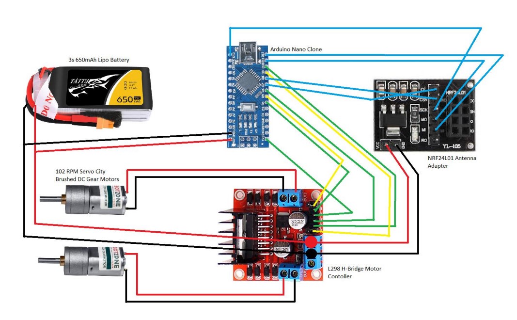
- Two 102 RPM Brushed DC gear motors were used to drive the wheels
- Continuous GT2 belts and 3d printed pulleys were used to transmit torque from the motors to the wheels
- An Arduino based electrical system was used to receive an RF signal from a remote and provide control the rotation of the motors
Result
- With a protype of the electrical system on a breadboard, the car was able to drive remotely and turn
- With the final electrical system on the testing day, one side of the car was unable to drive, preventing the car from completing the obstacle course
Failure Analysis
- The failure was determined to have been caused by a bug in the Arduino code with the wrong pins being initialized to control one side of the car
- Another intermittent issue with loss of wireless connection was determined to be caused by electrical noise from the brushes of the DC motor
- To avoid these issues, an off-the-shelf electrical system should have been used, given the time constraints of the project, and my experience level designing Arduino-based systems at the time
Drill Press Vise
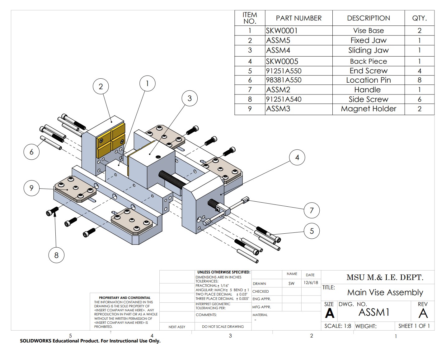
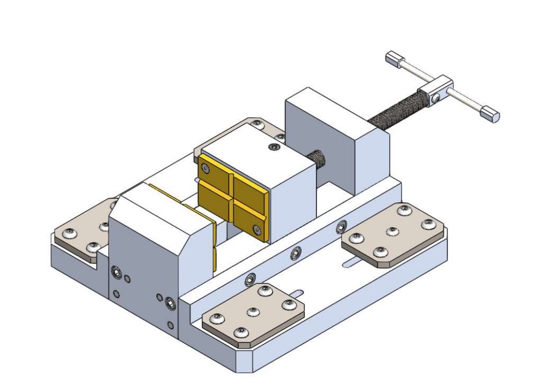
This was an in-class project that was designed in one class and manufactured in the next.
What
- A vise for holding material securely while it's being drilled with a drill press
- Had to be made primarily out of aluminum and be manufacturable with a manual mill and lathe
- Vise jaws and overall length had to fit dimensions specified by the class instructor
- Tolerances had to be correct for vise to fit together properly, and be machinable on available equipment
How
- 3 alternative designs were generated, then evaluated with a decision matrix
- The selected design would use electromagnets to securely hold the vise to the drill press table, and allow for easy repositioning between drilling operations
- The selected design was modeled in Solidworks, and a drawing package was created
Result
- Dimensions and tolerances of the design were deemed correct for the vise to function as intended
- Several parts of the vise were manufactured to within the specifications of the drawings, but the vise wasn't completed due to issues with machine availability
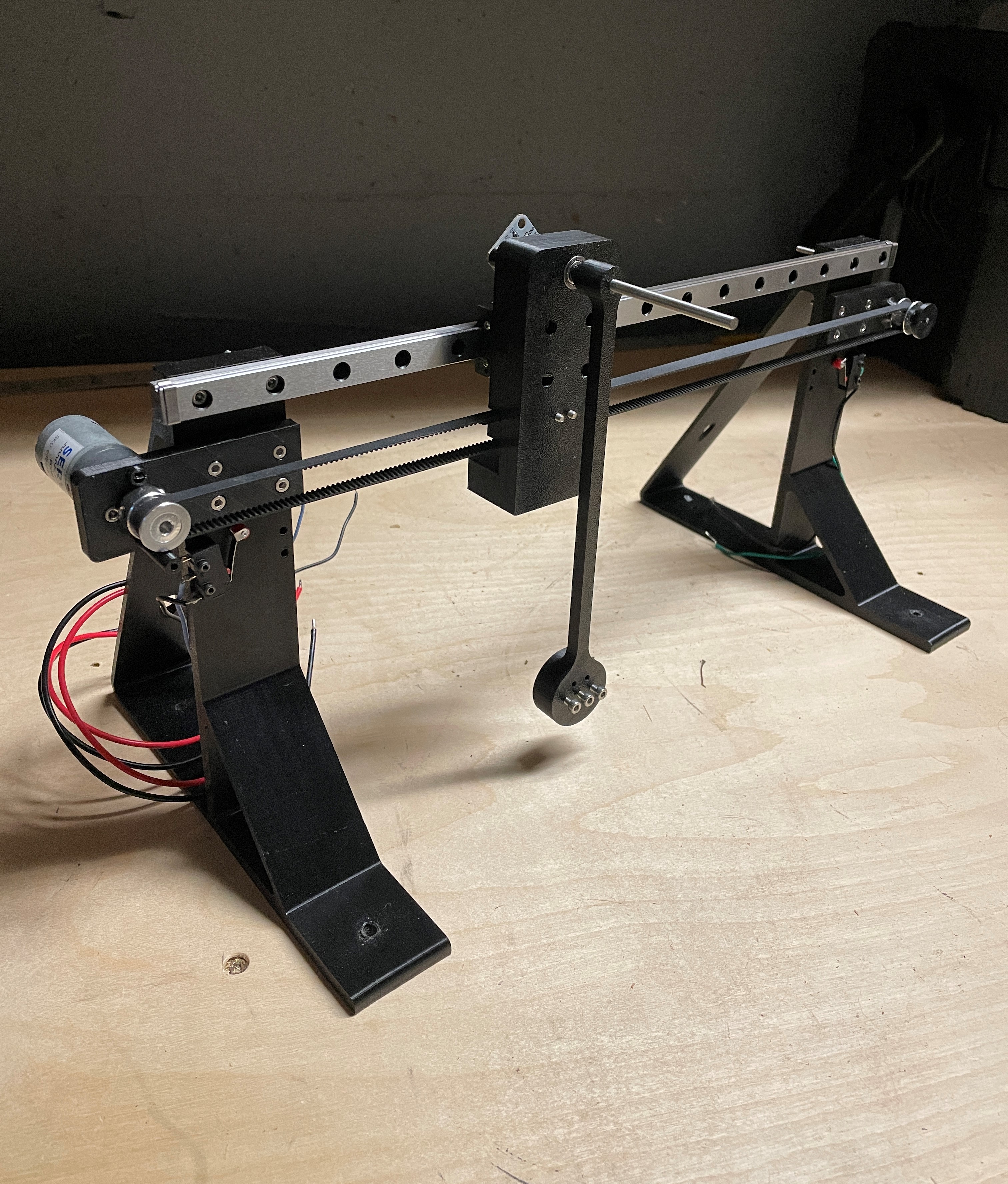
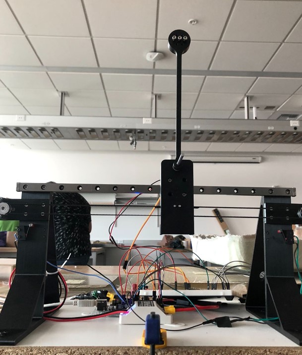
Inverted Pendulum
This was the final project for my Intro to Mechatronics class and was a group project with me and one other person.
What
- Project to demonstrate a mechatronics system, required to use a microcontroller and PID control
- We decided to implement a linearly translating carriage that would stabilize an inverted pendulum mounted to the carriage
How
- Designed components in Autodesk inventor and 3d printed them using an FDM printer
- Used a linear rail for translational motion of the carriage and ball bearings for rotational motion of the pendulum
- Used a small 12v brushed DC gear motor
- Used a GT2 timing belt and pulleys to translate rotation from the motor to translation of the carriage
- Used a magnetic encoder to read position of the pendulum
Result
- Pendulum was able to balance for around a second or two before drifting to one side
- Better results could be achieved with a combination of a longer pendulum, larger linear travel distance, more powerful motor and a more complex control system
Servo Controller
This was the final project for my Intro to Embedded Systems class.
What
- Used an MSP430 micro controller to read a potentiometer position and turn a small servo motor in response to turning of the potentiometer
- LEDs indicated when the potentiometer reached the halfway point
- Had to demonstrate the use of three peripherals of the MSP430, three interrupt service routines, and two external devices
How
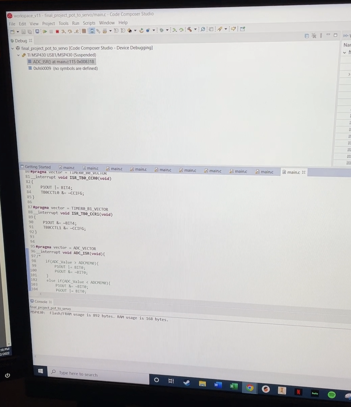
- Code for the MSP430 was written in C
- The three peripherals used were: Digital I/O for the LEDs, timers for the PWM to drive the servo, and the analog to digital converter to read the potentiometer position
- Two interrupt service routines were used with the timer to drive the PWM signal, and the third was triggered when the ADC finished its conversion
- The value read by the ADC was mapped to a pulse duration value to drive the servo
Result
- The servo moved as expected in response to the turning of the potentiometer knob
- The LEDs properly indicated when the knob reached its halfway point

Contact Me
Email: skweston123@gmail.com
Phone: (206) 755-1856
LinkedIn: linkedin.com/in/sam-k-weston